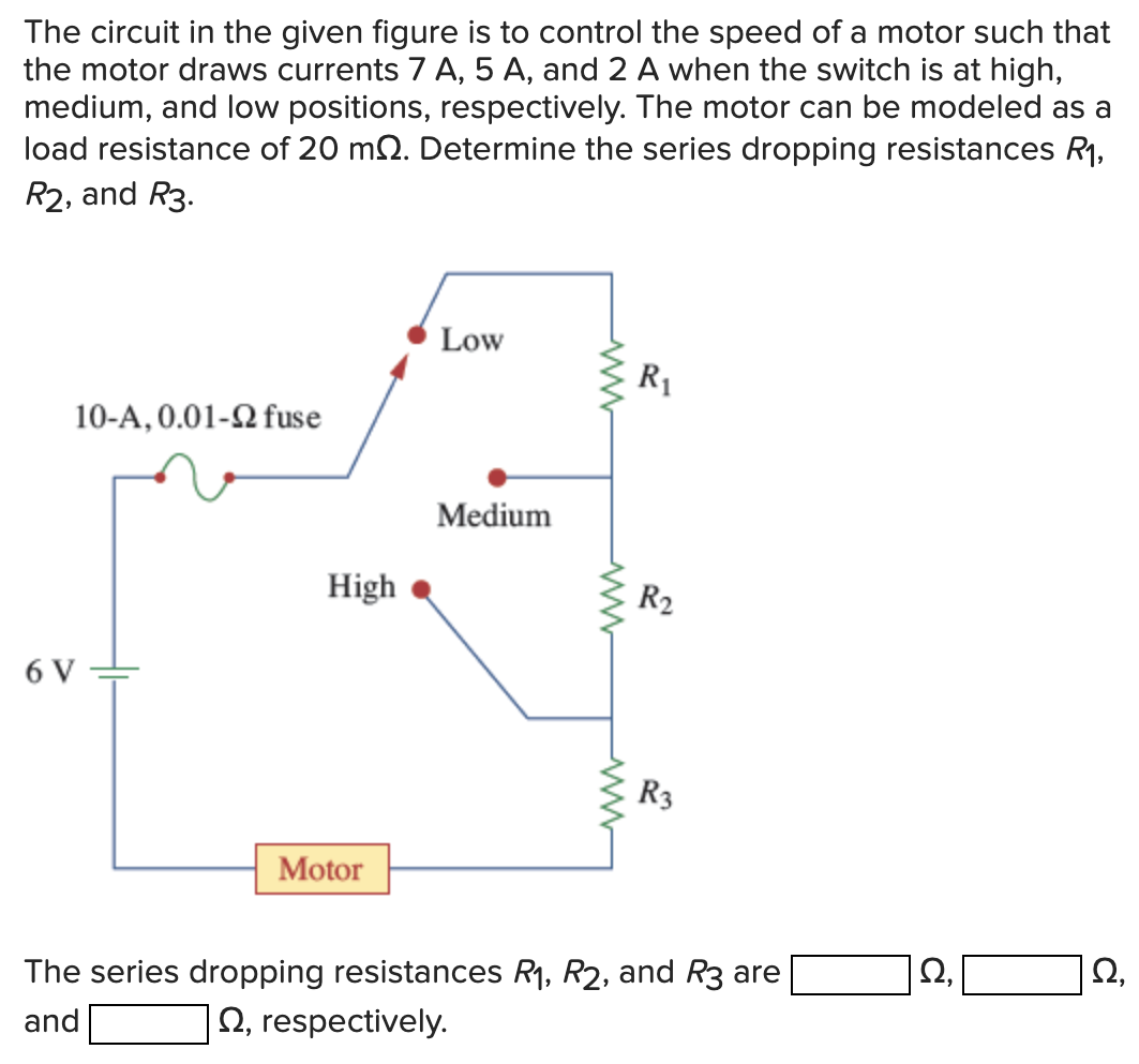
The circuit in the given figure is to control the speed of a motor such that the motor draws currents 7 A, 5 A, and 2 A when the switch is at high, medium, and low positions, respectively. The motor can be modeled as a load resistance of 20 mΩ. Determine the series dropping resistances R1, R2, and R3. The series dropping resistances R1, R2, and R3 are Ω, Ω, and Ω, respectively.
The circuit in the given figure is to control the speed of a motor such that the motor draws currents 7 A, 5 A, and 2 A when the switch is at high, medium, and low positions, respectively. The motor can be modeled as a load resistance of 20 mΩ. Determine the series dropping resistances R1, R2, and R3. The series dropping resistances R1, R2, and R3 are Ω, Ω, and Ω, respectively.

Image text
The circuit in the given figure is to control the speed of a motor such that the motor draws currents 7 A , 5 A , and 2 A when the switch is at high, medium, and low positions, respectively. The motor can be modeled as a load resistance of 20 m Ω . Determine the series dropping resistances R 1 , R 2 , and R 3 .
The series dropping resistances R 1 , R 2 , and R 3 are Ω , Ω , and Ω , respectively.

Detailed Answer

Answer
  • Student Reviews:
  • (3)
  • Correct answers (3)
  • Complete solution (3)
  • Step-by-step solution (3)
  • Fully explained (3)